Parallel Port FPGA Interface
I developed an interface between a Digilent Pegasus FPGA board and a Linux PC. The communication occurs via the PC's parallel port.
The main goals of this project were to learn Verilog, to learn about buses, and to create a platform for future projects which require the parallelism and/or exact timing of an FPGA combined with the ease of programming of a general purpose PC. An example of a future project is a programmable function generator. At the command of an application running on the PC, the FPGA can generate square waves or PWM signals to feed into a device under test. This is most useful if the PC also controls other instruments, such as an oscilloscope connected via GPIB.
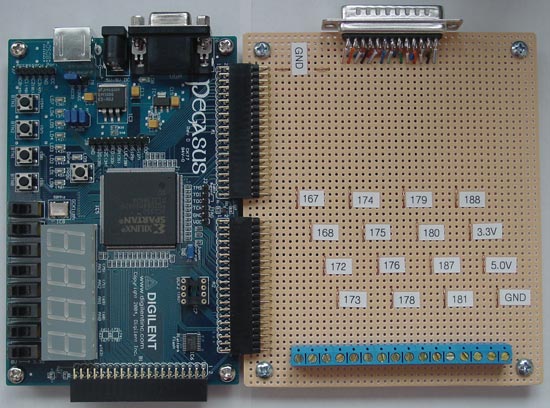
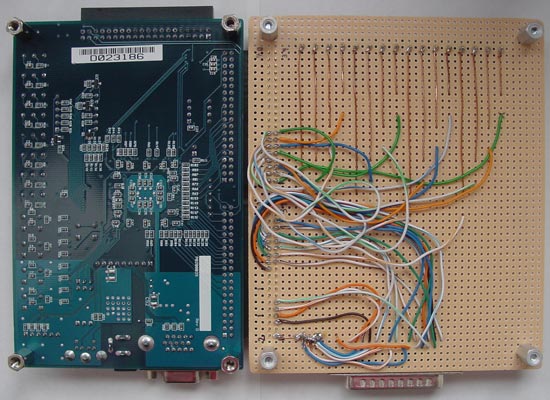
The pictures below show the Pegasus board attached to a custom interface board. The DB-25 connector is the parallel port interface. The custom board also features probe points and screw terminals for 13 FPGA I/O pins. For a mapping of FPGA pins to parallel port pins, please refer to the .ucf file contained in the Verilog code distribution and the EPP signal table at Beyond Logic.


|


